Page last updated: 29/04/22
Layout and location evidence revisited (Aug 2019 to May 2020)
Author: Mike Rogers (Outdoor Team Volunteer)
1. Introduction
The existence of a parterre in the Elizabethan Garden at Lyveden New Bield (a National Trust property in Northamptonshire) has been known for many decades, but due to agricultural use of the land in the area in the mid to late 1900s, all evidence of its form and location had been lost. Since the early 2000s, in order to highlight its existence, a pastiche of what was thought to have been the original design has been mown in the grass near its original location. As new evidence came to light, the mown pattern and its location has been modified a number of times to reflect that new knowledge.
Individually, none of the evidence available provides information that can be used to precisely define the parterre location, or its form (design). This review of the evidence attempts (once again) to determine those details.
The following lists that evidence in order of importance.
A. Luftwaffe Aerial Photograph
This reconnaissance photograph was initially believed to have been taken by the Luftwaffe, and is generally known by that name. It is now believed to have been an RAF photograph taken in 1944. Throughout this report, it is referred to as the ‘Luft image’. This image provides the most significant evidence of the parterre location.
B. Col. Brown Aerial Photographs
There are a number of photographs of Lyveden taken from the air at different angles. Believed to have be taken between 1930 and 1932, these provide additional visual evidence of the parterre, and proved useful in confirming the parterre location relative to the Lodge.
C. Col. Brown Archaeological Survey Report.
Dated 1934, this report by Col. Kenneth Brown is believed to have been written following his visit to Lyveden in 1932. At that time, some evidence of the parterre was still visible on the ground.
D. The Tresham POOLE and H.T.L.A Drawing dated 11/13
Investigations of historic documents by Clare Bense (Lyveden volunteer) show that Sir Thomas used a unit of length measurement that he called a ‘POOLE’, which he defined as being 18′ long. A drawing produced by HTLA also uses this definition and shows the layout of the primary garden features at Lyveden, and their dimensional relationships in terms of the Tresham ‘Poole’. Throughout this report, feet (ft) and Tresham ‘Pooles’ are used for the unit of length.
E. RAF Aerial image dated 1947.
This image is dated 28 May 1947. It is very similar to the ‘Luft image’, though the parterre lines are not quite as clear.
F. JNNHS Aerial image c1930.
Another photograph of the Lodge believed, like Col. Brown’s images, to have been taken in the early 1930s.
G. Brown and Taylor Report.
This report by Brown & Taylor (not Col. Brown) in 1979 differs significantly from the earlier Col Brown report, stating that “. . . slight traces in the field below it of a diamond-patterned knot, some 60.9 m (200ft) long by 30.4 m (100ft)“. No further details of the parterre are given, other than a diagram (also of 5 diamond patterns) similar to that of Col Brown’s report. Unfortunately, the diagram conflicts with the report’s own stated dimensions for the parterre. Having been researched some 40 years later than Col Brown’s report and photographs, it is likely that the area will have undergone more agricultural disturbance. In addition, during the year before this report, a new track had been installed between the parterre and the building resulting in a significant amount of re-grading of the land around the area. Despite its lack of consistency, the report does confirm that some visual evidence of the original parterre still existed in the late 1970s. For the purposes of this investigation, this report provides no additional useful information, and is not considered further.
In section 2, the information provided by each of the above images/documents (listed A to F) is investigated in more detail.
It is hoped that as a result of this investigation, decisions can be made that will define the parterre SHAPE, SIZE, and LOCATION. Individually, the validity of these pieces of evidence can be questioned and are occasionally contradictory. However, it is possible to draw some conclusions which allow the number of options to be narrowed down. In the end, the Trust will need to decide which option to choose.
- Note1. A number of images are embedded in this report which are displayed at a reduced size. Clicking on an image will open a new browser tab to display the image at full size.
- Note2. Both Col. Brown’s photographs and the ‘Luft image’ show a hedge (or hedge and fence, or hedge and ditch combination) just north of the parterre position, and running east/west across the parterre meadow. It is assumed that this was planted/constructed in the first decade of 1900 or earlier, and was grubbed out in the second half of that century when the whole meadow became intensively farmed. This hedge line is a key feature in identifying the parterre location.
- Note3. The New Bield building is generally called the ‘Lodge’. That title is also used in this report.
- Note4. The National Trust are keen to ensure that the depiction of the parterre accurately reflects the evidence available, and carried out their own investigation in 2009/2010, with a report being issued in January 2010. Their review concentrated primarily on two aerial images – the ‘Luft image’ and the ‘JNNHS image’, and concluded that on the ‘Luft image’, there were two additional lines faintly visible to the west of the lines that are relatively clear on the image. Based on that assumption, the report’s finding were that the pattern to be mown on the ground should be much wider than previously depicted, and as a result, a wide parterre pattern has been mown since 2010. The JNNHS image has been ‘lifted’ from that report for inclusion in this review.
2. Review of Parterre Evidence
2.1. Luft Image c1944.
2.1.1. From the original image, a section was taken covering the full extent of the Lyveden New Bield property (see FIG 1).

By zooming onto the parterre area, it can be seen that the visible parterre lines are not perfectly straight, but appear to have something of a ’kink’ about halfway along their length. If zooming in too far, the lines become so blurred that they are no longer discernable. A central E/W line is also just noticeable, but only over a short length of the parterre.
While the ‘kink’ (or disturbance/interruption) appears on all lines, it is not consistent in its magnitude. However, it is generally in the middle – where the two rows of triangles meet.

2.1.2. The image also shows a hedge line (apparently newly planted) crossing the parterre field W-E, with the parterre lines, in most cases, meeting this hedge line. (See FIG 2.) The hedge itself appears to be planted as a single row of plants. At first glance, a second row appears just behind (to the north) of the first. This second row, on closer inspection, appears to be a shadow of the first row shown against a lighter background. The lighter background itself, could be a narrow raised bank indicating a slight rise in ground level above the parterre area. Another explanation could be that there is a narrow ditch crossing the field just north of the hedge, and the lighter patch is the (north) bank of the ditch.

2.1.3. Using LibreOffice Draw, lines were added to highlight the parterre lines on this image which was then calibrated using mapping software (MapMaker) to rotate and re-scale the image to the UK OS grid. This re-scaling was achieved by defining two reference points on the image, and entering their GPS positions which were established using the website ‘gridreferencefinder.com’. The two points used here were the centre of the ‘Lodge’ (GPS location 498403E 285311N), and the point on Harley Way some 200 metres west of the Manor House entrance, where a drainage ditch passes under the road (GPS location 497901E 285989N). A copy of this calibrated image can be seen in FIG 3.
2.1.4. Once calibrated, the distance from the ‘Lodge’ centre to the hedge line could be measured. Due to the difficulty of defining these points precisely, a number of readings were taken, which varied by +/- 2 ft. From these measurements, an average figure of 437ft (A) was calculated. This distance measurement will be used in calculations in section 2.2 below.
2.1.5. On this image, five parterre lines can be readily identified. Having added this calibrated image to the mapping software as a new layer, the distance between these five lines was measured a number of times, and the average of these readings produced a figure of 358.797ft between line 1 and line 5.

2.1.6. The Luft image suggests that the northern edge of the parterre is parallel to (or on the same line as) the hedge. It also appears that the parterre has been set out at right angles to the Lodge N/S centre line. If this is the case, then the hedge line should also be at right angles to the Lodge N/S centre line. Using the mapping software, this was tested using this ‘Luft image’ by placing two markers on the hedge line, one on each side of the Lodge centre line, and equidistant from it. The distance from these markers to the Lodge centre was then measured, and gave figures of 554ft on the west side, and 556ft on the east side – see FIG 4. QED?
2.2. Col Brown Photographs c1930.
2.2.1. There is one obvious anomaly when comparing the Col Brown photographs with the ‘Luft image’. On the Col. Brown photos reportedly taken in the early 1930s, the hedge is a dense, well established feature, with a gap about half way along its length. On the ‘Luft image’, apparently taken 10 years later, there is no obvious gap, and the hedge appears very thin suggesting either that it had recently been planted, or it is a fence rather than a hedge with occasional plants and a tree along its length. This difference could be explained if it is assumed that at some point in time between the two images being taken, the old hedge was grubbed out and replaced by a new fence/hedge. If that is not the case, then the ‘Luft image’ must have been taken some 10 years before the Col Brown images. However, it is felt that this anomaly does not degrade the validity of the evidence relating to the parterre location.
A significant benefit of the Col. Brown images is that both NW to SE lines, and NE to SW lines can be seen which confirms the diamond pattern anticipated. However, the central E/W line suggested on the ‘Luft image’ is not apparent here.
Unfortunately, the Col Brown photographs lack the benefit of the ‘Luft image’ because they were taken from a much lower altitude, and cannot readily be converted to provide a scaled image for mapping purposes.
2.2.2. Col Brown’s photographs are significant in that they clearly show the diamond pattern described in the various reports. The most useful of these images was taken from the west of the parterre – see FIG 5 .

None of Col Brown’s images show the north edge, a centre path, or the south edge of the parterre. However, it is possible to establish an approximation of those positions by highlighting the lines that can be seen, in order to determine where they meet (on the north and southern edge of the parterre), or cross (on the parterre E/W centre line).
In order to use the image shown in FIG 5, and to use the distance between the Lodge and the hedge established in para 2.1.2. above, we first need to determine the north/south centre line of the Lodge. To achieve this, three other Col Brown images were used. On each of these, a line was drawn across the top of the Lodge, in line with the building’s centre line. This drawn line was extended northwards to the hedge line. A copy of that drawn line was then moved down to ground level where it was felt that it represented an imaginary line through the centre of the Lodge at its ground level. The purpose of this was to find the point where the Lodge centre line meets the hedge. Obviously, there is a significant risk of error in this determination, and for that reason, this procedure was repeated on different images, one taken from the south, one from the south west, and one from the west. The result of all three tests can be seen in FIG 6, FIG 7, and FIG 8 below – click on images to view in detail.


It can be seen that in all three cases, the Lodge centre line appears to meet the hedge at a point to the east of the gap in the hedge referred to in para 2.2.1.
2.2.3. Returning to the Col Brown image of FIG 5, lines were drawn on this image to highlight the seven parterre lines clearly visible. Of these, 4 follow the NE – SW side of the diamond pattern, and 3 the NW – SE side of the pattern. The north edge of the diamond pattern as now drawn appears to be very close to, or even on the hedge line (as suggested on the ‘Luft image’).

A line (AA) was drawn representing a line through the N/S centre of the Lodge at ground level, to a point east of the gap in the hedge line as established in 3.5 above. (Interestingly, this line suggests that the parterre was not necessarily centred around the ‘Lodge’ centre line.) Another line (BB) was added to the drawing to mark the centre line of the hedge. Line CC was added, drawn through the three points where the parterre lines crossed, and representing the E/W centre of the parterre pattern. The southern end of the diamonds appear to be in line with the south edge of a wider, darker patch of ground. This edge was also marked by adding another line (DD) passing through the two points which mark the southern end of the completed diamond shapes. Finally, a line (EE) was added to represent a vertical line down through the N/S – E/W centre of the Lodge. Where line AA and EE meet represents the mid point of the Lodge at ground level. The resulting drawing can be seen in FIG 9.
The primary purpose here was to establish the centre position of the parterre pattern relative to the centre of the Lodge. This can now be calculated by measuring the length of the line from Lodge centre to hedge (a distance of 437ft (A) established in 2.1.4 above), and from Lodge centre to line CC (parterre E/W centre). The two lengths are 141.34 and 114.38 respectively. Using these figures, (437/141.34)*114.38, the distance from Lodge centre to parterre centre =353.6ft (B).
A second measurement from Lodge centre to line DD (which represents the southern edge of the parterre) can be used to calculate this position. The two measurements from the drawing are 141.34 and 90.62 giving a distance from Lodge centre to parterre southern edge = 280.2ft (C).
Both these calculated dimensions are only a guide to support or contradict more precisely established figures.
2.2.4. Col Brown’s photograph FIG 5 also appears to show a path from the north of the cottage heading north, past the end of an unknown feature (possibly a ditch) and heading towards the southern side of the parterre. From there it changes direction, going east and skirting the southern edge of the parterre. At the end of the parterre, the path appears to head north again to the hedge corner. The question why the path skirted the parterre rather than taking the shorter route straight across is not known. The only reason it is mentioned here is in case it could have some relevance to the parterre itself, or is it just a coincidence? At this time, we do not know.
2.3. Colonel Brown Report.
2.3.1. Col. Brown’s report is believed to have been based on his observations during a survey of the property in 1932 which was around the time he took a series of photographs of the New Bield. It is believed that the report was not published until 1935.

Col. Brown survey report drawing
In his report, Col Brown described the parterre as follows: “The New Building was built on a raised square five feet high by three hundred feet square, this was probably all grass. Two hundred and twenty five feet from the main door and on the same axis was a formal garden, four hundred and seventy five feet by one hundred and fifty, and this was laid out in a diamond pattern and was probably the flower garden.”
The diagram (see FIG 10) of the Elizabethan garden, New Bield and parterre given in that report shows the parterre as a feature of two rows of triangle shapes centred on the Lodge north/south centre line. The pattern is enclosed in a rectangular border, which, together with the central path produces 2 split triangles on each side to the array.

FIG 11 reproduces a section of the drawing (covering the New Bield and parterre), that section having been rotated onto north/south axis. It is, perhaps, interesting to note that Col. Brown’s description refers to the parterre as being “laid out in a diamond pattern“, whereas his diagram, with its central path splitting the diamonds, has the effect of creating two rows of nine triangles.
The drawing shows that the overall width of the pattern is wider than the New Bield plinth, with the western edge almost in line with the outer edge of the east spiral mount moat. The relationship between parterre width, and New Bield plinth width is consistent with the dimensions in his description.
2.4. The Tresham POOLE.
2.4.1. Clare Bense started volunteering at Lyveden in the late 1990 and undertook some investigative work examining letters written by Sir Thomas Tresham which had been discovered some years earlier, and were held at the British Library. Amongst these letters, she came across one that was written on the 9th Oct 1597 and specifies that “Within the walls it is 108 yards square. Which of 18 foot to the poole, containeth 18 pooles.”
This definition is taken into consideration later in this report to determine the location of the parterre relative to the Lodge.
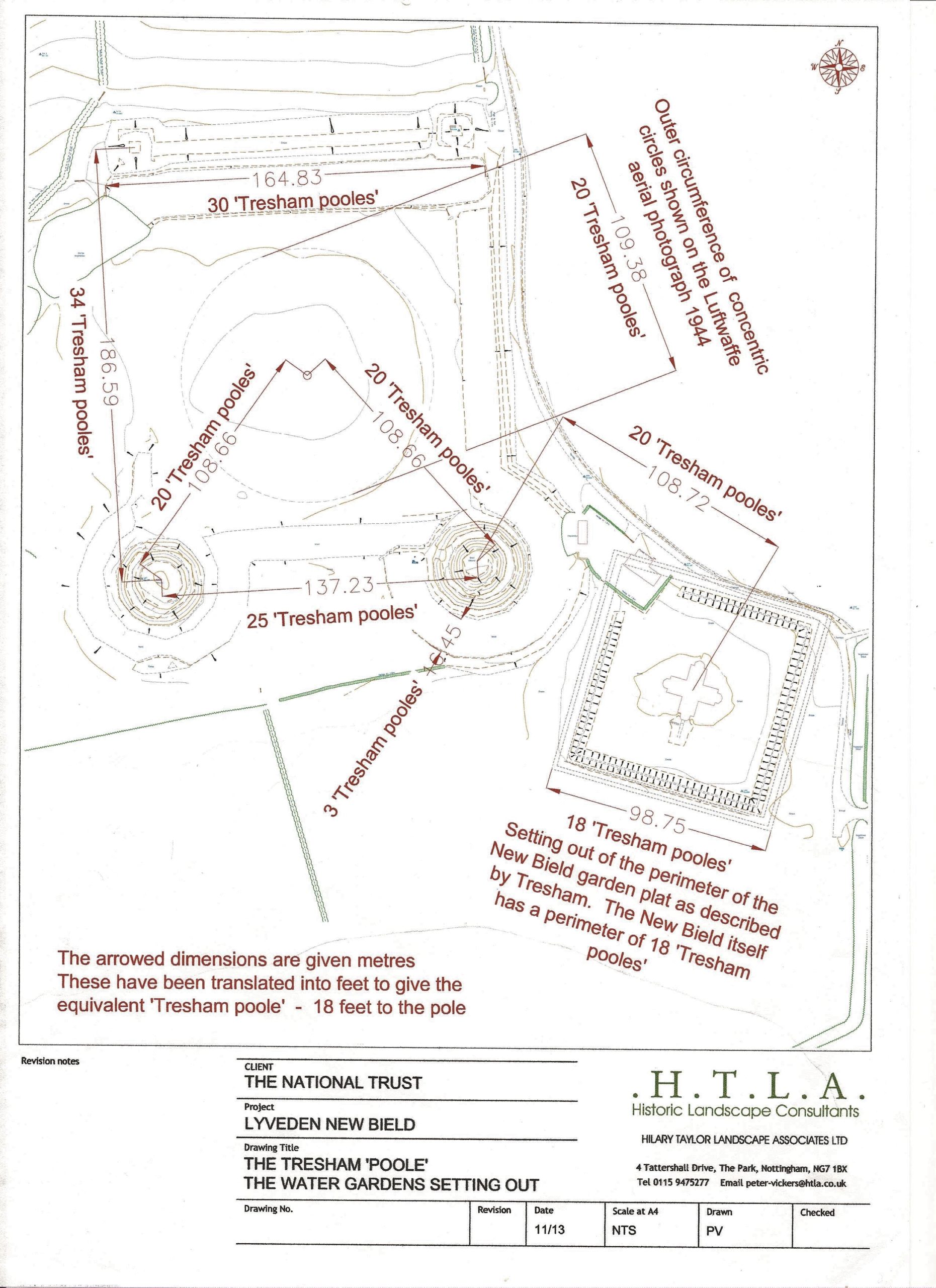
2.4.2. In 2013, H.T.L.A. (Hilary Taylor Landscape Associates Ltd.) carried out a survey covering Lyveden’s Elizabethan garden. That work produced a map entitled “The Tresham ‘Poole’ – The Water Garden Setting Out”. The map, which defines the Tresham ‘Poole’ as a length of 18ft, shows all the primary garden features (Spiral Mounts, Pyramidal Mounts, Terrace, Moats and the New Bield and its platform) and provides dimensions for the distance between some of the features as listed below:
| New Bield centre to East Spiral Mount centre | 20 Tresham ‘Pooles’ |
| East Spiral Mount centre to Labyrinth centre | 20 Tresham ‘Pooles’ |
| West Spiral Mount centre to Labyrinth centre | 20 Tresham ‘Pooles’ |
| Labyrinth diameter | 20 Tresham ‘Pooles’ |
| East Spiral Mount centre to West Spiral Mount centre | 25 Tresham ‘Pooles’ |
| Total length of Terrace and the two Pyramidal Mounts | 30 Tresham ‘Pooles’ |
| Distance between West Spiral Mount and West Pyramidal Mount | 34 Tresham ‘Pooles’ |
A copy of the H.T.L.A drawing can be seen in FIG 12.
2.5. RAF Aerial image – dated 1944.

2.5.1 This image (see FIG 13) was dated around the same time as the ‘Luft image’, and had a number of similarities, namely:
- Five parterre lines are evident, all NW-SE.
- There are no obvious corresponding NE-SW lines.
- The hedge (or combination hedge/fence) north of the parterre is not dense, or overgrown, and without the obvious gaps seen in Col. Brown’s photos. It could have been recently planted.
- The hedge line appears to be on the same line as the northern edge of the parterre.
- The hedge is made up of a single row of plants which appears to be on the south side of a ditch or bank – see section 2.1.2. describing this feature as seen on the ‘Luft image’.
This image differed slightly from the ‘Luff image’ in that it does not show either a central line, or any significant ‘kink’ in the parterre lines.

Lines were added to this drawing to hightlight the visible lines on the image (see FIG 14). Lines 1-5 appear to correspond with the parterre marking seen on the ‘Luft image’ and Col Brown’s photographs. Line 6 is an anomaly. The spacing is wrong for it to be part of the parterre, and the marking on the ground is different. In this case, it is a ‘lighter’ marking, where all the others are darker markings (see FIG 13). Line 7 would appear to correspond with the ‘path’ seen on Col Brown’s image, and described in section 2.2.4.
2.6. JNNHS image c1930s

Although this image only covers the western part of the parterre meadow, it is useful in that it confirms some of the evidence available from the other images.
Similar to Col. Brown’s aerial images, the hedge line north of the Lodge appear ‘bushy’ in comparison with the ‘Luft image’, and has the gap in it at about the same point (see section 2.2 above).

There are two parterre lines evident in this image, and (like Col. Brown’s images) confirms the belief that there were NE-SW lines in addition to the NW-SE lines shown on the ‘Luft image’. A central E-W line is not apparent here, but this image does tend to confirm that the lines did meet the hedge line – once again suggesting that the hedge was planted on the northern edge of the parterre pattern. FIG 16 hightlights the two parterre lines, with the furthest west one meeting the hedge just before the gap in the hedge, and the second one meeting the hedge line in that gap. These are consistent with the second and third line (counting from the west) on Col. Brown’s photograph (FIG 9).
3. Conclusions.
The parterre design (shape), size, and location relative to the New Bield building cannot be determined precisely from the sources of information listed in section 2 above. However, there are some clues and coincidences that would firmly suggest a solution to these issues.
3.1 Parterre design.
3.1.1. Summary of evidence:
- Thomas Tresham frequently symbolised his religious beliefs by the use of triangles.
- Another building of Sir Thomas’s (the Triangular Lodge) used equilateral triangles as the basis for its design.
- Col. Brown’s report described the parterre as based on ‘diamonds’ yet his own drawing of the parterre shows triangles.
- Col. Brown’s aerial photographs indicated a parterre pattern based on diamonds and triangles.
- While the ‘Luft image’ suggested the possibility of a central east-west line through the parterre pattern, the RAF and JNNHS images tended (though not definitely) to negate that possibility.
- Two images (Col.Brown’s and the JNNHS images) confirm that there were (at least some) corresponding NE-SW lines to match the NW-SE lines seen on the ‘Luft image’.
- There is no photographic evidence of a border surrounding the pattern, other than the hedge line on the north side, and a disturbed patch of ground on the south side.
- A pattern of diamonds and triangles, or just triangles, is dependent on the existence or not of the central path. The photographic evidence suggests that this path did not exist; while the written evidence tells the opposite. In section 4 below, this report provides examples of both options.
3.2 Parterre size.
3.2.1. The H.T.L.A drawing demonstrated Sir Thomas’s use of the ‘Tresham Poole’ (18ft) as a unit of measurement. The Lodge itself is 5 ‘pooles’ (90 ft) wide/long.
3.2.2. Parterre height (N-S). The ‘Luft image’ showed 5 lines of the parterre, these averaging a total of 359ft apart (see 2.1.3 above). This would indicate a line separation distance of 89.75ft, or 5 ‘Tresham Pooles’ (90ft). ‘5’ is also a number of significance to Sir Thomas.

Equilateral triangles based on 90ft sides will have a height of 78ft. Therefore, the height of a double row of these triangles (making a diamond pattern) would be 156 ft. (see FIG 17). Col. Brown’s survey report recorded the parterre ‘height’ as being 150ft, a difference of 6ft, or 4%.
This report concludes that the parterre design was probably based on 5 ‘poole’ equilateral triangles. This conclusion will be tested when the parterre design using this principle is checked against the ‘Luft image’ in section 4 below.
3.2.3. Parterre width (E-W). The ‘Luft image’ clearly shows 5 parterre NW/SE lines. If we assume, as indicated on Col. Brown’s aerial photograph (see FIG 5) and the JNNHS image (see FIG 16), that there were 5 matching NE/SW lines, and that the lines are 5 ‘pooles’ apart, then the total width would be 450ft. Col. Brown’s survey report recorded the parterre width (E-W) as being 475ft. This difference (slightly greater than 5%) could be caused by measurement error, or could be down to the difficulty of precisely defining the location of the parterre lines. An alternative explanation could be that Col. Brown took diagonal measurements in order to confirm that the parterre was rectangular rather than trapesoidal or some other quadrilateral shape. If that was the case, then the measurement for the 5 ‘poole’ design parterre would have been 476ft, surprisingly close to Col. Brown’s measurement. This explanation is the only one that matches the scaled width measured from the ‘Luft image’ – see section 2.1.5.
In the absence of any other compelling evidence, this report concludes that the parterre width was 450ft as indicated on the ‘Luft image’.
3.3 Parterre North/South position relative to the Lodge Centre.
3.3.1. In section 2.2.3. the calculated distance between the ‘Lodge’ centre and the parterre E/W centre line was in the order of 353ft. The H.T.L.A. drawing established the distance between the Lodge centre and the East Spiral Mount centre was 20 ‘pooles’. This was also the case for the distance between other garden features. It is proposed that this 20 ‘poole’ figure (360ft.) should also be used for the Lodge/parterre spacing, to see if this assumption is valid when example designs are compared with the ‘Luft image’. If that assumption is confirmed, it would suggest an error in Col. Brown’s measurement of 7ft (just under 2%).
3.4 Parterre axial position relative to the Lodge.
3.4.1. Col. Brown’s survey report states that the parterre is “two hundred and twenty five feet from the main door and on the same axis“.
To enable this “same axis” statement to be confirmed, it would be necessary to determine with a reasonable degree of accuracy, the GPS coordinates of the New Bield axis so that it could be added to the calibrated ‘Luft image’.
This was achieved as described below, and shown on FIG 18.

- (1) The centre line of the Lodge was located visually and marked at a number of points on the ground north of the Lodge (in parterre meadow). GPS readings were taken at a number of points on this line. Note, the GPS receiver is a Garmin ‘Etrex Venture HC’ hand held device. It provides readings of current GPS position to a resolution of 1m, but is only capable of achieving an accuracy of +/- 10m. [[These readings were taken for information only, and are marked on the map with yellow ‘stars’ (*) – see FIG 18. A straight line was drawn on the map passing as close as possible through these points to mark the Bield centre line as determined by these readings. It is noticeable that the result produces a line which is approximately 2.5 metres west of the true Bield centre line.]]
- (2) Two points (speed reducing bumps) were identified on the (Park Lane) road surface next to parterre meadow, these points being clearly visible on satellite images. Using ‘GridReferenceFinder.com’, GPS readings were taken for these two points.
- (3) For each of these points, a length measurement was taken from each point to the Bield centre line as determined at (1) above. The measurements were 20.75m for the most northerly speed bump, and 79.27m for the southern speed bump. Additional checks were undertaken to ensure that these values were the minimum possible – i.e. perpendicular to the Bield centre line.
- (4) On the mapping software, circles were drawn centred on each speed bump, using the relevant radius measured in (3). A straight (chord) line was drawn from western edge of the northern circle to the Bield centre. This line also touched the western edge of the larger circle suggesting that this line accurately identified the New Bield centre line.
- (5) For future reference, a straight line passing through grid reference 498487 (E) 285609 (N) and the Lodge centre at 498403 (E) 285311 (E) will represent the Lodge north/south axis.
3.4.2. FIG 19 is a map showing the Bield centre line (established in 3.4.1.) with the ‘Luft image’ in the background. Since the Bield itself is in the same place on both map and ‘Luft image’, it would seem that the parterre pattern was centred slightly to the west of Bield centre line. This discrepancy is in the order of 8ft.

It is likely that the parterre was intended to be aligned centrally to the Lodge, but was in fact slightly to the west of that line. The question to be answered is, should the depiction of the parterre be put where it actually was, or where it was intended – a decision for the National Trust. This report offers examples of both options below.
4. Possible Parterre Design Examples.
4.1. Design Layout
The featured designs below are all based on the conclusions of this investigation, namely the 5 ‘poole’ equilateral triangle, and a 20 ‘poole’ spacing between Bield E/W centre to Parterre E/W centre. When these designs were added to the mapping software, IT WAS FOUND THAT THE RESULTING PARTERRE PATTERNS MATCHED VERY CLOSELY THE ‘LUFT IMAGE’.
For each example below, four ‘birds eye’ views of the parterre are provided:
- View A – parterre centred (on the Bield centre line) with the ‘Luft image’ in the background;
- View B – with the parterre offset to give a ‘best fit’ result to the ‘Luft image’;
- View C -with a background of a 2019 image captured from Google earth:
- View D -and one showing the featured parterre without a background.
The National Trust will need to decide which (if any) of these parterre layouts will, in future, be depicted on the ground. Each has its own advantages and disadvantages in relation to accessibility for visitors, ease of mowing, and marking out. To quote a comment made in 2010 – “if we are replicating a feature, we should be doing it as accurately as the available evidence allows“.
Note. ‘View C’ showing the proposed new layout with the Google earth image in the background provides an example of the difference between the current mown pattern, and that proposed. The most noticeable difference is that the new layout has the pattern rotated slightly anti-clockwise. This change is primarily as a consequence of establishing the Lodge N/S axis more accurately, and results in a position difference approaching 20ft at the north/west corner of the pattern. A further difference, as a result of the 5 ‘poole’ equilateral triangle use, is a slight ‘narrowing’ of the pattern width, and widening of the pattern height.
4.2 Examples
4.2.1. MIN 1 version
This is the basic parterre pattern of diamonds and triangles, and possibly meets Col. Brown’s report description most accurately. The layout produces 4 central diamonds with two rows of 5 triangles, one row on the north side of the diamonds, and one (inverted) on the south side.


4.2.2. MIN 2 version
For this parterre pattern, an E/W central path has the effect of splitting the diamonds in half, resulting in 2 rows of 9 triangles. Possibly more typical of Sir Thomas’s designs?


4.2.3. MIN 3 version
By adding an enclosing border at the east and west ends of the parterre, this version meets Col. Brown’s drawn plan of the parterre, rather than his description.


4.2.4. MAX version
As described in NOTE 4 in section 1, an earlier Trust investigation came to the conclusion that the parterre extended to both east and west to cover the full width on the parterre meadow. This report questions that conclusion on the basis of a lack of evidence, written or photographic. This version does, however, offer the advantage that it provides more visitor access points onto the parterre.
For this example, no ‘best fit’ view B is shown, as this was never considered for the ‘MAX’ layout.


5. A Speculative Observation
The belief that Sir Thomas’s garden design placed two garden features 20 ‘pooles’ away from the ‘Lodge’ centre could be taken a step further. Was it to be his intention to have other features constructed around the Bield on that same radius?

To see if any evidence appears on the ‘Luft image’ at this distance, a 20 ‘poole’ circle centred on the Bield was draw (using a dashed black line) on the map. See FIG 20.
Looking at the image, there appears to be nothing obvious to support that idea, but it is interesting that the circle just touches the S/E and S/W corners of the parterre.
As an additional check, an isosceles triangle was drawn connecting the centre of the 3 features – Bield, parterre, and East Spiral Mount. A copy of that triangle was made, and placed in an anticlockwise direction adjacent to the first triangle. It then seemed that a total of 5 such triangles might complete the circle.
5? Sir Thomas? Surely there must be something in this?
To test this, an isosceles triangle with two equal sides of 20 ‘pooles’, and an angle opposite the base of 72 (360/5) degrees was drawn. This was placed on the map, replacing the first one. As expected, the other side of the triangle appeared to to be in line the centre of the east spiral mount.

4 more triangles were created and placed around the Lodge centre starting from the first – see fig 21.

Finally, the ‘Luft image’ was added in the background in the expectation (or hope) that something would be found – see FIG 22.
But still nothing obvious.
It was quite a surprise to find that the parterre and east spiral mount were almost exactly positioned at the corners of a segment equal to one fifth of the circle. Was it just a coincidence, or did Sir Thomas have further plans for his garden, which like the Bield itself, would never be completed?
End of report.